Medical device manufacturers are constantly looking for ways to gain an edge in a competitive global marketplace. But the pressure to drive innovation often results in a narrow focus on the product and less emphasis on the methods by which it’s made. Nicholas Eidem, Advanced Powder Products director of business development, explains why it’s important to design products with a mode of production like metal injection moulding in mind.
The origins of metal injection moulding date back to the 1930s, but it wasn’t until the 1970s that the process started to grow in use.
Even after experiencing success during this period, it didn’t become a commercially viable choice for manufacturers until the late 1990s.
Now, many of the top medical device OEMs are using MIM to manufacture components used in surgical instrumentation, robotic surgery, dental and orthodontic equipment, drug delivery systems, implants, and multiple orthopaedic applications.
Despite this impressive resume, many engineers are still hesitant or unfamiliar with incorporating MIM into their designs over conventional processes they are accustomed to, such as computer numerical control (CNC) machining.
What they may not realise is that MIM has many advantages over CNC machining, including material flexibility, scalability, design freedom, and most importantly component cost.
But realising the advantages of MIM requires a strategic approach to component design, and once a part is designed for machining or another manufacturing process, it is often too late to switch.
How does metal injection moulding work?
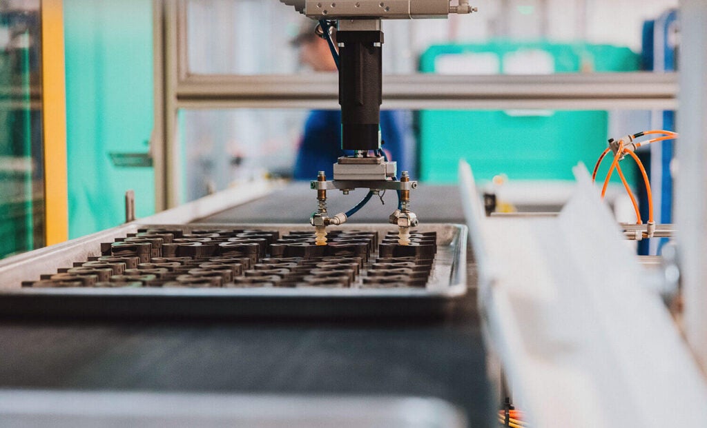
The process of MIM works similarly to micro injection moulding plastic parts, but uses metal powders mixed with polymers to form them instead.
The tooling and equipment used to process MIM components are virtually identical, and engineers accustomed to plastics will see familiar equipment in a MIM production factory.
Another contrast between plastic and MIM moulding is that there’s more variation in the quality of end products with the latter.
This is because the MIM process requires additional steps that are unique and predicated more upon the technology capabilities of the processor, rather than established industry practices.
The MIM process is very much a science and, like any scientific discipline, it operates according to a set of principles.
First, a hypothesis is created, which in the case of MIM is characterised as a set of rules to design experiments around.
These principles lead to the creation of a stable and scalable production process that includes feedstock compounding, the injection moulding process itself, catalytic or solvent debinding, sintering, and secondary processing.
The MIM process can be used to manufacture a wide variety of materials and alloys.
Once a material is selected, the process starts with formulating feedstock – a combination of fine metal powders and binders, such as waxes and different polymers.
Once cooled, the feedstock is granulated into pellets to prepare for injection moulding.
To ensure reliability and repeatability during processing, the feedstock compounding process is tightly controlled.
The MIM sintering stage occurs when the moulded parts are placed in a high-temperature furnace.
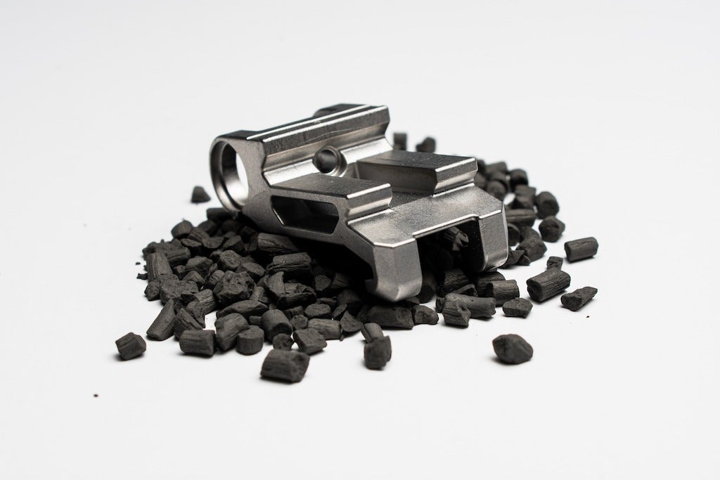
The part is heated near its melting point, all the remaining binder is completely removed and the metal particles are bonded together.
The part then shrinks and densifies, and the final strength and geometry of the metal part are formed.
This stage is where part geometry is most important; because the moulded part is heated near its melting point and shrinks up to 20%, gravity greatly impacts the component.
It’s for this reason that component designers must consult with MIM experts to factor the shrink and distortion into the form, fit, and function.
This can be easily overcome with the use of sintering fixtures, and dimensional capability remains excellent, with tolerances plus or minus 0.5% on average.
What makes a good medical metal injection moulded part?
When evaluating and designing a component for metal injection moulding, one of the most common questions asked is ‘what materials can you MIM’?
A good part is typically made from ferrous alloys such as carbon steels, stainless steels, and tool steels.
If a material has a high enough melting temperature and the powders are available in the appropriate size, it can most likely be created using MIM.
This rules out non-ferrous alloys such as zinc and aluminium, and medical device engineers need to ensure alloys will pass FDA and biocompatibility testing.
Fortunately, MIM can process a wide variety of nickel-based and cobalt-chrome alloys that are widely accepted and have a documented track record within the FDA.
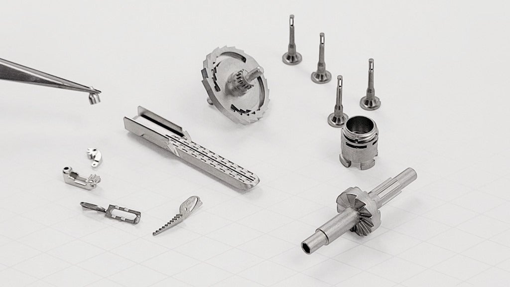
After material selection, the next characteristic to consider when designing for metal injection moulding is component mass.
The mass of a good MIM part is typically under 30g, with the average being 5–15g.
The rule of thumb for the size of a MIM part is that it should fit in the palm of your hand.
MIM parts can vary from 2mm to 150mm – with the average being around 25mm.
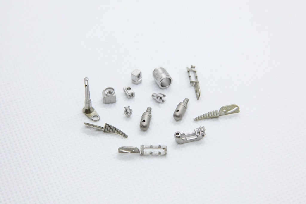
A subcategory of MIM is micro metal injection moulding, which focuses on components that weigh less than a gram and have distinctly intricate features.
When designing and manufacturing micro MIM components, heightened awareness must be placed on tooling strategy as well as feedstock and material selection.
Micro components require special feedstocks designed to properly mould small features.
MIM producers that have in-house feedstock formulation and material expertise are well-positioned to tackle micro components.
What to consider when designing a part?
Wall thickness can be a larger concern with MIM when compared with other forms of manufacturing.
This is due to alloy material mould flow properties; walls much smaller than 0.010in will have a difficult time filling and packing completely because of high shear forces limiting flow and/or air entrapment.
While on the subject of wall thickness, a good MIM part will also have a relatively uniform thickness throughout.
If a part has drastically different wall thicknesses, then the thinner features will sinter sooner than the thicker areas – causing distortion.
One way to alleviate this issue is to core out the thicker areas of the part.
A good MIM part will rely on radius corners rather than sharp corners; sharp internal corners are undesirable because the material can pull a void in those areas during the injection phase.
Additionally, sharp external corners in the part require a sharp internal corner in the tooling, which is very difficult and costly to produce.
As a rule of thumb, it’s good to avoid designing a part with an edge radius smaller than 0.005 to 0.006in.
Like plastics, a good MIM part can still have undercuts and threads – but these do require more complicated tooling.
The tooling will need to have cams or side actions to form undercuts; they slide into place before the mould closes and slide out of the way before the part ejects from
the tool.
As one might expect, this also increases the cost of the tool; however, in macro terms, the return on investment is better than having each part machined secondarily to make the undercut – especially at higher unit volumes.
Threads can be integrated into the tool, but there needs to be ‘flats’ on the sides of the threads to accommodate a flat parting line.
Metal injection moulding versus machining
Assuming that the availability of programming, machines and labour input is there, machining might seem like the most appropriate process methodology for small precision metallic components.
In terms of speed to market, including prototyping, CNC machining is a strong contender.
When considering a machined approach, things like tools, fixturing and work holding requirements are often significant constraints, especially as the complexity of parts increases.
The higher the Rockwell rating – a measure of the hardness of the material – the more difficult machining becomes, as feedstock and processing speeds need to be altered.
The most advantageous aspect MIM brings is the ability to scale the process up into a repeatable, consistent, and high-tolerance production process, especially as the component complexity escalates.
In terms of value, MIM provides a significant cost advantage of CNC machining once production requirements get into the thousands.
Why consult with an expert?
The overarching issue most design or manufacturing engineers make, when approaching a micro metal component requirement, is overlooking MIM entirely.
As outlined earlier, MIM is a relatively new process that is often incorrectly associated as a sub-niche within the context of pressed powdered metals – this is an errant assumption.
The technology, from alloy formation all the way through to the vacuum sintering phase, differs entirely from any other metallic shape processing method.
Successfully working with the MIM process requires collaboration between the device designer and those with technical expertise at the processing company.
The technical competency of the MIM provider will quickly ascertain if any given design will successfully work in the MIM process.


